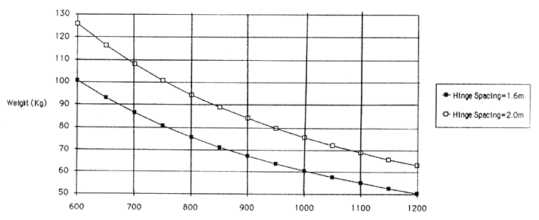
Interpretation of hinge loading charts
The following calculations were supplied by Abbott & Associates, Consulting Engineers.
The preceding graphs of allowable door weights are shown for two hinges per door spaced at 2.0m (upper line) and 1.6m (lower line) and are based on the following assumptions –
Due to the significantly greater strengths of the hinge in the direction of the axis of the pin, the loading in this direction has been ignored.
- A factor of Safety of 4 has been used.
- No allowance has been made for additional loads from forces such as wind, earthquake, slamming or door closers.
- Fixings appropriate to the materials used in the construction of the door frame or panel are the responsibility of the door manufacturer.
- Test loadings to elastic limit were provided by Material Testing Laboratories, 172G Marua Road, Panmure, Auckland.
When referring to the charts, use the top curve with white squares for 2.4m high doors (2m spacing between top and bottom hinges) and the bottom curve with black squares for 2m high doors (1.6m spacing between top and bottom hinges).

For example, a 2m high door 1000mm wide allows a door weight of 60kg for 100mm/7 hole hinge and 138kg approx. for the Heavy Duty 110mm/7 hole hinge. Please note that the above does not include calculations for door closers.
The Heavy Duty hinge only should be used in these situations. You will notice that the higher the door and the greater the distance between top and bottom hinges, the greater the allowable door weight.
Maximum loading is on the top and bottom hinges which are in tension and compression respectively while the load on the middle hinge is neutral. Where four hinges are used some of the load on the top hinge is spread to the second hinge provided the door jamb is fixed securely to eliminate distortion. As a general rule the top and bottom hinges should be positioned as close as possible to the top and the bottom of the door panel.
Top hung door closer applications
It is not possible to calculate accurately the hinge loading effect of top hung door closers because of both the variety of closers available and the variety of possible installations. To minimise the effect the following recommendations should be followed –
- Position the top hinge as close as possible to the top of the door panel.
- Attach the closer arm to the door panel as far away from the hinge side of the door panel as is practical without affecting the operation of the closer itself.
- Adjust the closer to close the door gradually and avoid any sudden slowing or stopping action.
- Ensure hinges are fastened securely to the door panel and door frame (refer installation details below) and that the frame is packed between frame and stud in the hinge area.
As a general guide we recommend for the purposes of calculating allowable door weight that the actual door weight be increased by 20% for non back check door closers and by 100% for back check closers. As an additional precaution 4 hinges should be used. Where the door width exceeds 1000mm the spacing between the two top and two bottom hinges should be 25% or less of the door height with the space between the two middle hinges being the remaining 50%.


